Page 1 of 2 12 LastLast
Results 1 to 10 of 13

Thread: engine control panel restoration

  1. #1
    Member geracing2000's Avatar
    Join Date
    Mar 2012
    Location
    Pescara, Italy
    Posts
    30

    engine control panel restoration

    Hi all,
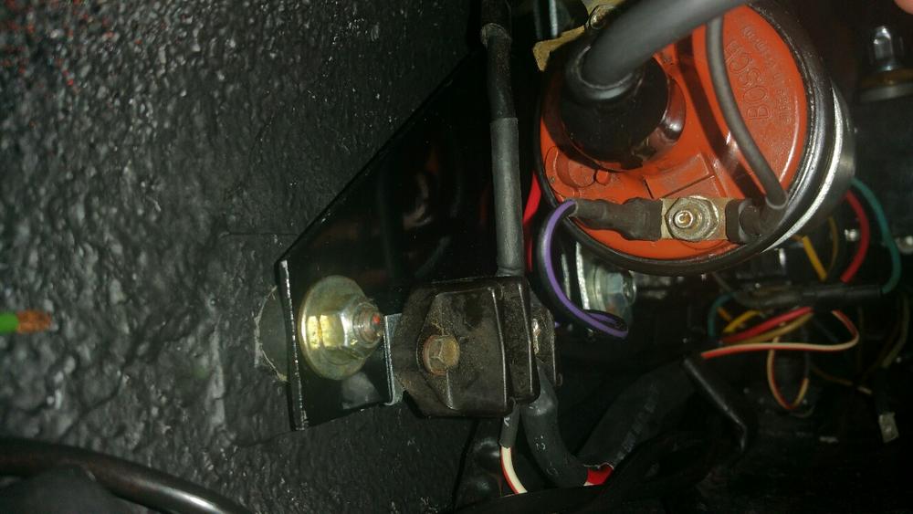
    after the deep reading of your precious "electrical" threads i' ve almost completed my 1968 S engine control panel restoration. Please find attached some pics. Before firing up the car i would appreciate your comments and suggestions, expecially regarding the 2 poles junction block wires connections.

    Name:  20150429_124542_resized.jpg
Views: 508
Size:  102.7 KB
    Name:  20150429_124732_resized.jpg
Views: 496
Size:  98.6 KB
    Name:  20150429_124556_resized.jpg
Views: 508
Size:  88.6 KB
    Name:  20150429_124648_resized.jpg
Views: 503
Size:  66.9 KB

  2. #2
    Senior Member
    Join Date
    Oct 2010
    Location
    Southern Ca.
    Posts
    1,170
    Looks good . The two pole junction block is for the battery wire from the alternator and the wire that goes to the starter . They go together .as pictured .

  3. #3
    See if it starts,,,,,if it does you did it correctly
    Early S Registry member #90
    R Gruppe member #138
    Fort Worth Tx.

  4. #4
    Member geracing2000's Avatar
    Join Date
    Mar 2012
    Location
    Pescara, Italy
    Posts
    30
    Thank you Richy!
    to edmayo...i hope i did it correctly otherwise i will see flames from the engine bay!

  5. #5
    Good, correct '68 ballast resistor. Make sure the resistance value is 0.9 ohms. I don't know what that coil is, maybe from an Opel? What is part number on the bottom and what is primary resistance measured between the screw terminals (you will have to disconnect everything).

    Un-tape the points lead from the distributor wire-- you don't want crosstalk between the two.

    Switched +12v in the single end of the wye, one output fuel pump, other to ballast resistor relay. See this:


    Double and triple check everything and have a fire extinguisher handy when you connect the battery and turn the key on! Pericolo di Morte!

    Good luck!
    1966 911 #304065 Irischgruen

  6. #6
    Looks to be an unattached ground wire behind fuel pump.
    Early S Registry member #90
    R Gruppe member #138
    Fort Worth Tx.

  7. #7
    Member geracing2000's Avatar
    Join Date
    Mar 2012
    Location
    Pescara, Italy
    Posts
    30
    Hi gents.
    I did some resistance checks ob ballast resistor and coil. The first gave me a value of 1.2 ohm and the second 2.1. 304065, are these value correct? I followed your drawing and i have connected alle the wires in the right places. Thank you very much!
    Regarding the type of coil it is a vw one, maybe installed on a jetta. I have two of them. Please see the picture below. Bosch code should be the one that was used to supersede the factory installation code.
    Edmayo, you're right, the ground wire was not connected when i took theese pictures. Now it's connected correctly to the chassis and the electrical aluminum board.
    Please let me know in i'm out of "pericolo di morte"!!!

    Name:  20150505_133112_resized.jpg
Views: 319
Size:  59.8 KB

  8. #8
    Ge,

    Why did Porsche use a ballast resistor on the SWB cars?

    For starting-- when the starter motor is running it pulls the battery current available for the ignition system down. In order to deliver acceptable current to the ignition system for starting, they used a coil with a resistor in series for normal operation- then when the starter motor was running, the resistor was bypassed, allowing a similar level of current to pass to the coil so the engine would start when cold.

    This is why there is an external resistor-- so it can be bypassed. If they just made the primary resistance of the coil higher, it would only have two modes- low, and so low that it won't start!

    All right. One other limitation of the 1960s Kettering-Ignition is that the points can switch a maximum of about four amps. Any higher than that and they will not last or function reliably. So . . . a little ohm's law:

    12V (nominal) battery voltage divided by four amps = 3 ohms primary resistance. If you look at the original SWB coils, they have a 2.1 ohm primary resistance. The early ones look like this, they are a little different for '68.


    Now, that is used with a 0.9 ohm ballast resistor. . . 2.1 + 0.9 = 3 ohms, for four amp maximum points current.

    Your setup. . . 1.2 ohm resistor + 2.1 ohm coil = 3.3 ohms primary resistance, for 3.64 amps maximum points current! This practically means that you will experience more difficult starting when cold, and at HIGH rpm, you MIGHT experience ignition breakup, just when you need it the most!

    For more reading about WHY this happens see here:

    http://www.early911sregistry.org/for...d-NOS-SWB-Coil

    The SHORT version (Ed is chuckling, he knows I don't HAVE a SHORT version!) is that the amount of ignition energy that builds up in the coil between sparks is a function of battery voltage and coil primary resistance and time. The longer you have, the more a lower amperage current can build up the magnetic field. . . but when the time shortens between ignition events, at high rpm, there is not enough time to charge the coil between sparks, leading to a fall-off in performance.

    So. . . my recommendation is to either a) see if you can find a lower-resistance ceramic ballast resistor, such as off a Mercedes of the period, if you can't find a Porsche one, or b) source a lower-resistance coil (which may be hard to find).

    Maybe like this? See the 0.9?


    Hope this helps! PLEASE let me know if you have questions.
    1966 911 #304065 Irischgruen

  9. #9
    Member geracing2000's Avatar
    Join Date
    Mar 2012
    Location
    Pescara, Italy
    Posts
    30
    Thank you for all the inputs you are giving me. I really appreciate your technical support to all the forum community.
    Just one question. If i touch the two leads of my multimeter i read 0.3 omhs, due to the resistance of the multimeter wires, i guess. Does it make any sense to subtract 0.3 omhs to every measurement? In that case i would have 0.9 for ballast, 1.9 for the coil and around 4.2 amps to the points...

  10. #10
    Ge, Bravo! You have found the problem! Yes, if your multimeter does not zero out the ohms measurement, then it is measuring the resistance of the test leads AND the resistor in series. It is likely that your ballast is 0.9 (you can see it stamped on the side, or take a photo and post it here), the coil, being a VW Jetta part, was likely designed for electronic ignition that uses a solid-state transistor to switch the coil current, and as such can handle a few more amps (Modern Bosch stuff switches like 10A)-- so it has lower primary resistance, that makes sense.

    At 4.2 amps to the points I would be OK with operating it, this should not be a problem.
    1966 911 #304065 Irischgruen

Posting Permissions

  • You may not post new threads
  • You may not post replies
  • You may not post attachments
  • You may not edit your posts
  •  

Message Board Disclaimer and Terms of Use
This is a public forum. Messages posted here can be viewed by the public. The Early 911S Registry is not responsible for messages posted in its online forums, and any message will express the views of the author and not the Early 911S Registry. Use of online forums shall constitute the agreement of the user not to post anything of religious or political content, false and defamatory, inaccurate, abusive, vulgar, hateful, harassing, obscene, profane, sexually oriented, threatening, invasive of a person's privacy, or otherwise to violate the law and the further agreement of the user to be solely responsible for and hold the Early 911S Registry harmless in the event of any claim based on their message. Any viewer who finds a message objectionable should contact us immediately by email. The Early 911S Registry has the ability to remove objectionable messages and we will make every effort to do so, within a reasonable time frame, if we determine that removal is necessary.