Results 1 to 7 of 7

Thread: 69 Electrics Question

  1. #1
    Member
    Join Date
    Jun 2015
    Location
    Connecticut
    Posts
    51

    69 Electrics Question

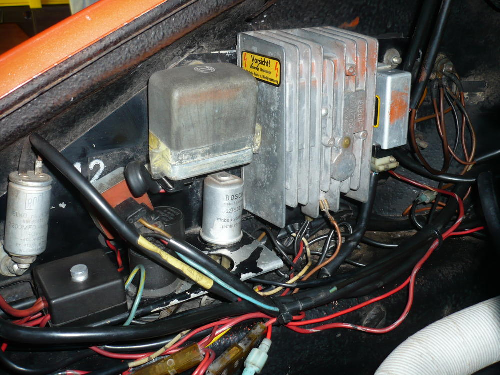
    I have a question about the Bosch Tach adapter p/n 0 227 990 001 wired with the Bosch CDI on my 69 911T. This is a cylindrical 3 Pin silver can. Wiring diagram SL 33 refers to it as "Switching SCR" for the 69E/S Models and SL 35 calls it the "Intermediate Unit", for the 70T/E/S Models. In another picture of the (71) electrics in the factory manual it is called the "RPM Sensor".

    From what I have read in Pelican forums and in the PET catalogue, it is also referred to as a "Ballast Resistor". Some have opened it up to take a look and make measurements and it bears no resemblance to what I think of is an SCR (Semi-conductor Controlled Rectifier). Is the part misidentified in the SL 33 factory manual?

    My connections do not match the wiring diagram either. I have the high voltage lead from the CDI going to one pin, a second pin feeds the ignition coil transformer terminal A and the third pin feeds the Tach, I guess. If it was an SCR where is the controlling pulse coming from?

    Another oddity I can't identify is the can on the left which looks like a radio noise suppressor . It is a 2 pin cylinder (ELKO 2200MFD written on body), one pin gets switched power and the second ground pin goes to the CDI ground terminal.

    I might add that it all seems to work, so what am I worrying about! Just trying to make sense of it all. Unfortunate, there is no specific wiring diagram in the factory manual for the 69T, so the best we have to work with is the SL 33 version.

    Name:  P1040622.jpg
Views: 1310
Size:  133.5 KB
    J P
    69 911T 2.4L w' 2.2S/E cams/Webers

  2. #2
    Not sure what your question is, but remember you're dealing with translations to English. It is more commonly referred to as an intermediate unit, or at least that's what I've heard the most. There isn't any high tension lead from the C.D. box, that takes place at the ignition coil. Pin 'a' of the "intermediate unit" is grounded, maybe at the external ground pin of the C.D. box in your picture. Pin 'c' does go to the tach.
    Early S Registry member #90
    R Gruppe member #138
    Fort Worth Tx.

  3. #3
    Member
    Join Date
    Jun 2015
    Location
    Connecticut
    Posts
    51
    Thanks edmayo.
    I don't seem to have a ground connection on my 3 pin intermediate unit. One pin is hooked up to a white/brown wire from the CD box. One pin uses the same color white/brown wire and goes to the ignition coil, One pin is a black wire going to the tach we assume. In the SL 33 wiring diagram pin 'a' goes to ground, pin 'b' goes to coil, pin 'c' goes to the tach. I understand there are translation issues but describing functionality like an SCR is not the same thing as a Ballast Resistor. Anyway, I thought the SCR triggering was done inside the CD box.
    Then there is the 2 pin ELKO gizmo on the left which gets power on one pin and a brown wire on the other pin going to the external CD ground pin. Can't figure out its function either.
    J P
    69 911T 2.4L w' 2.2S/E cams/Webers

  4. #4
    Senior Member
    Join Date
    May 2012
    Location
    ITALY
    Posts
    124
    ...My connections do not match the wiring diagram either....
    If your car is a '69 MY (VIN 119......) you have a later engine fuse panel.

  5. #5
    Here's the wiring diagram

    http://forums.pelicanparts.com/porsc...-pre-74-a.html

    The ELKO gizmo is an ignition noise supression capacitor that came with the radio kit.

    Here's what's happening-- from 1964 until October, 1970, the tachometer was triggered by a high-voltage (24V) square wave pulse.

    After October, 1970 the tachs were modified to run off an 11 volt square wave. You can tell by the date code and the tach input being labeled "C" instead of "/1"

    Now, CDI was introduced for the 1969 model year for the E and S. Somebody has added a Bosch CDI to your panel or installed one from an E or S-- in the original T the CDI was added on well forward of the fuel pump. Your fuel pump appears to be missing.

    When the CDI was added the current in the points circuit went from a huge EMF pulse down to a little 420mA current-- not enough to trigger the old style tach. So the intermediate unit was added, it's basically a voltage divider, to trigger the tach.
    1966 911 #304065 Irischgruen

  6. #6
    Member
    Join Date
    Jun 2015
    Location
    Connecticut
    Posts
    51
    It is a 69 fgmec but the CDI was added later(76).

    Thanks John, I read the Tach-oh-woe thread recently. Most of my questions are as a result of it because the InterEurope wiring diagrams were so close to my setup. Only discrepancies are the ones I have noted. I'm pretty happy with the explanation about the function of the intermediate unit, if not the connections. I am currently running the Crane XR700 optical ignition triggering system but that is upstream of the CD box. The fuel pump is missing because because after a string of fuel pump failures(6), I have a Holley(very loud) attached to the rear torsion tube which I am getting ready to relocate to the front cross member.

    Thanks for identifying the ELKO radio noise suppressor. Next time I get to the tach I will check the label & date.
    J P
    69 911T 2.4L w' 2.2S/E cams/Webers

  7. #7
    JP, you can shed a few pounds by ditching a redundant ignition system . . . or two

    Are you saying you are just using the crane trigger in the distributor, or the entire thing including the black box with fins? That's a standalone, optically triggered (go figure) electronic ignition system which you would use with a specific coil.

    If just the trigger, then the optical is replacing the points to trigger the CDI, it should behave like an on-off switch just like the points, so the current flow in the circuit is the same 420mA, it's set by the 33ohm pull up resistor in the CDI itself.

    The thing about Warren's InterEurope diagrams is that they show the Intermediate Unit (that's what we call it) hooked to the 350V output from the CDI. That's how we know it's a voltage divider!

    remember this

    A=Achtung = 350v
    B= Batterie = +12v
    C= Contact = points trigger
    D= ground
    1966 911 #304065 Irischgruen

Posting Permissions

  • You may not post new threads
  • You may not post replies
  • You may not post attachments
  • You may not edit your posts
  •  

Message Board Disclaimer and Terms of Use
This is a public forum. Messages posted here can be viewed by the public. The Early 911S Registry is not responsible for messages posted in its online forums, and any message will express the views of the author and not the Early 911S Registry. Use of online forums shall constitute the agreement of the user not to post anything of religious or political content, false and defamatory, inaccurate, abusive, vulgar, hateful, harassing, obscene, profane, sexually oriented, threatening, invasive of a person's privacy, or otherwise to violate the law and the further agreement of the user to be solely responsible for and hold the Early 911S Registry harmless in the event of any claim based on their message. Any viewer who finds a message objectionable should contact us immediately by email. The Early 911S Registry has the ability to remove objectionable messages and we will make every effort to do so, within a reasonable time frame, if we determine that removal is necessary.