
Excellent tip Torch - I absolutely agree. I did in fact swap out for a new copper crush washer between the pressure sender and that mounting bolt. Thank you for the message!


Excellent tip Torch - I absolutely agree. I did in fact swap out for a new copper crush washer between the pressure sender and that mounting bolt. Thank you for the message!
Thanks for spec/link for the 7mm fuel line....bought 2 meters
73.5 Snrf T
71 Snrf T
70S targa
76 914 2.0
82 Targa,
85 Alfa GTV6
60 Lancia Appia Zagato GTE
Searching for transmission 7115322 (911/01)
You got it 71gold - and on that topic, I have been working more on sorting out fuel delivery today.
As promised, here is a review of that line. (the 7mm I.D. line). Keep in mind, this is for any of the 8mm O.D. breather pieces. For example, the bottom of the air cleaner / oil drain. That is an 8mm fitting, same with the other end of it.
This is how it is delivered.
Here it is up close:
"MADE IN GERMANY" is visible and the quality of the cloth weave is awesome. It is tightly woven (as opposed to that URO line) and is clearly a great quality line. 14 bucks to your door? Totally worth it. I recommend this 7mm line all day.
Now for a shout out to Paul Abbott. Paul not only stands by his work, he quickly becomes a friend. What a guy. He must have spent collectively 2-3 hours on the phone with me troubleshooting and another 2-3 hours in diagnosing my carbs for me. I happily paid him for the time spent. The information he taught me and the value of his documentation is priceless. We need more people like Paul - not just in this line of work - but in our offices, family's and so on. Just a stand up guy I can't say enough good about.
He originally rebuilt my webers a couple years back and due to the hard starting issues and other idle problems - he took them back in to diagnose while I have been working on all of the ignition, timing, valve adj, etc..
I finally (shipping has been weather clogged lately) received them back today.
They were always snappy, but let me add he cleaned them up again for me and helped dial them in. Further, he walked me through what tools to buy (synchrometer, etc..) to set everything up correctly. This stuff is so cool. I can read Paul's docs all day. As a matter of fact I just had a destination wedding over the last two weeks and on the plane I read most of his documents.
New top of the carb to "air cleaner boat" gaskets:
Set in place:
Setting the air cleaner boats in place:
There are four small flat head screws that hold the boat in place, and then the airhorns on top of that.
I will add, that there is clearly a "center" so I installed everything loose, and then aligned (shining a light down each throat) each air horn, and then finally each boat screw.
Then, onto blue-printing the throttle cross bar (per Paul's documentation - did I say his docs are awesome and fun to learn from?):
Look at how "off" it was! Almost 1/2":
Using a crescent wrench, I bent the arms so that it laid 100% flat. When I looked at the crossbar after seeing it was 1/2" off, there was clearly one side that was twisted, so I manipulated that one first.
Now that the throttle cross bar and all throttle linkage "blue-printed" and within OEM specifications. I was able to set everything back into place and call it a day. I need to wait for warmer weather when I can get the car up to temperature and dial in the air flow and idle speeds, timing and so forth.
New carb to manifold gaskets:
I apologize for the poor lighting in the garage. That's another project!
Do you guys have a source/part number for the rubber gaskets that are in the tops of the boats? The oval pieces you can see here, that the air cleaner sits on?
Thank you!
Couple of questions for you guys (maybe missed from above):
1. Does anyone have a part number/source for the oval air cleaner to carb gasket? (Top of the carb horns/boats to the main air cleaner body).
2. Spark plug wire routing. I see the right bank of carbs (4/5/6) the plug wires go under/through the intake manifold and rest in rubber grommets. I purchased a new set of plug wires from Stoddard and am wondering if/how to route them through there, since they are assembled. I am probably missing something obvious.
Thank you for any insight.

Nice work. As to the wires, you just unscrew the plug connector from the wire, its just a wood screw that screws into the copper wire, run the wires thru the grommets and reinstall the ends.
Early S Registry member #90
R Gruppe member #138
Fort Worth Tx.
Very good - I was hoping it was something simple that I was overlooking. Thank you for the direction, Ed! Much appreciated.
re: Spark Plug Wires
Thank you Ed, for the information and insight!
Upon further investigation, purchasing THESE from Stoddard.
After the above tip from Ed, and investigating both the plug wires on my car and this new set - I found the reason I was scratching my head with the "wood screw" suggestion.
Here is what you get when you peel back the 90 degree boot on the Stoddard set:
Note that the wire is continuous all the way to the tip/crimped on brass pieces the secures to the end of your spark plug. PRO: Continuous wire, no point of resistance or possible poor connection with the woodscrew. CON: They manufacture the set completely put together. There is NO WAY of feeding the wires through the intake manifold boots. You'd think you can just lube and slide off the smaller boots at the dizzy cap and go backwards, but they also fit on the three wire holder rubber pieces that push into the fan shroud, so there is no way to slide those off over the brass crimped on pieces. Argh. The only thing to do is cut the wire holders on the bottom, install wires and then re-glue or whatever the wire holders. Not the end of the world, but a pain.
Here is a spark plug wire that came off my car - one that fits Ed's description and makes sense:
The obvious bonus here is that you can install the wire through the rubber grommet at the base of the intake, reinstall the connector and you're off to the races.
I'll report back soon on the installation. I am working on a valve setting write-up and valve cover gaskets/oil change. Should be done this weekend or first of next week.
UPDATE 03/11:
After working with the above Stoddard spark plug wire set, I spent 45 min on the phone with Stoddard this morning (Paul - very helpful) going over why THESE WILL NOT WORK on your early 911.
1. Snap connection for end of the spark plug nipple is 1/2 the size of OEM - obviously forcing you to screw off the end and expose the threaded stud:
Like so:
Not only that, but since the snap is too small for the nipple, it is then too big for the threaded post and does nothing more than chew up the threads on the spark plug.
2. The spark plug connector is 13mm shorter than the OEM connector. WHAT?
This bonus feature requires you to then sink the connector further into the valve cover, rendering the "elephant ear" or dust boot/seal absolutely useless because it pushes in past the valve cover.
3. As pictured above, the set is pre-configured - not sure what they were thinking here, as there is no way to run them through the intake manifold on the right side. I tried everything, and the only option would be to disassemble/cut the rubber hold-down guides that plug into the fan shroud and a few other things. Even IF you wanted to route around the carbs, the wires are now in conflict with the throttle linkage. Not sure what car these were developed off of - and I even verified and validated the correct part number.
So, I cleaned up, tested and repaired the original spark plug wire set.
Unless they redesign these, buyer beware - they just won't work on your 2.0.
Last edited by dmaddox; 03-11-2021 at 02:55 PM.
Valve Adjusting fun:
Preaching to the choir here. Adjusting valves a topic that every Dempsey, factory and YouTube based manual or walk through leads you to believe is easy. I learn daily, even if I have adjusted hundreds of valves over a 30-year period of rebuilding engines, restoring cars and so forth. Being new to Porsche, nothing is really different here other than the awkward angles and access to the valves. Otherwise, the design/setup of the valves and the adjustment is no different from any other.
That being said, I thought Id provide some reviews and feedback on a few tools I have purchased and how I ended up adjusting the valves. To start things off, I have followed every procedure in the mentioned manuals, dropping the oil, removing the valve covers, having all new parts and materials in hand ready to go. A messy job, no doubt, making adjusting the valves on my 1978 Toyota FJ40 seem like a trip to the country club in comparison to assembling IKEA furniture in the Dagobah System.
I also found several items while doing this that needed attention. The vacuum ports on the intake manifolds were plugged with an interesting arrangement of bolts and a generous amount of Teflon tape.
Further, I found the passenger side to be leaking, causing a vacuum leak in both locations. (explains the bent throttle bar, to compensate heavily on the right bank.....sheesh)
The volume of teflon tape was impressive. Why? The plugs chosen were some SAE unit cut to fit.
I found the correct bolts to be 14mmx1.5mm pitch, 13mm long. I scoured the web for something other than a "big ol' bolt" that was designed for plugging vacuum lines. I found these:
They are exactly M14x1.5x13mm designed to plug vacuum lines and came with a crush washer. I chose these because I wanted a subtle/sleek design and not a bolt plugging the hole. If you are reading along, I ordered several to meet the minimum $$ order, so if these float your boat, hit me up.
Installed:
Part of the reason I decided to adjust the valves was not only because the car is new to me and I wanted to have the peace of mind and learn, but also to fix a bunch of leaks (as noted above).
There was also a leak on the oil filler neck and many of the hoses (as discussed earlier) needed to be replaced.
So, I disassembled the area and cleaned it up, replacing the filler neck rubber collar.
I then drained the oil from the sump, cleaning all sump plate surfaces and spiffed up the area. As you guys know that only gets 90% of the oil out, the remaining 10% is a bonus from your exhaust valve covers directly onto the manifold and onto everything else.
Once your face, exhaust manifolds, garage floor, hair, hands, and if youre having a great day, your teeth are sufficiently covered in used Swepco, we are off to the valves.
After setting #1 TDC on the 1Z line, I found the valves were tighter Tucos sample in the salvage yard. I had to recheck to ensure I was on #1 TDC! Not only that the 13mm lock nuts had at least 100ft pounds on them. Conan adjusted the valves last.
Now onto the tools....
Tool one: The Kirk tool (yes, very well engineered, very well put together, nifty and fun gadget that looks at home on the space station), is very difficult to use. Some people tout its amazing usefulness and ease; however, those people are aliens with 17 fingers. I had similar experiences to this guy: http://ponderingporsches.blogspot.co...d-sort-of.html. They are entirely too fidgety, clunky and wont seat on all of the adjusters, and then when it does, you have to apply pressure and hold onto the wheel while pressing on the set shaft ..to get it to seat while also tightening the set screw for it! Not to mention, upside down? Sorry, this tool is not for me. When I finally fought my way through the learning curve (it takes the careful involvement of both hands), you have to cheat on the line set a few times to see how much the thing turns past the .1mm mark when you tighten it. The instructions say to apply pressure on it, but you cant because youre holding onto the thing so it wont turn off the rocker arm and your other hand is working the 13mm. Bah. Total hassle.
Next, A feeler gauge, the old-fashioned way. In comparison to the Kirk tool, the feeler gauge is definitely easier to use, I set a couple and then to verify tried to fit a .005 in there and then a .003 to see if it wiggled. That way, I knew that even after dealing with the lock nut, etc.. I knew I could use two other feeler gauges and know I was spot on. This works, but is entirely time consuming and you have feeler gauges all over.
Snap Gap. What caught my eye about the Snap Gap system outside of great customer service and speedy shipping, was no feeler gauges, and spot on .004/.1mm on each valve, Locked in place and a hefty peace of mind knowing that everything is precisely on the money. The number 1 question I see on these is whats going to fall off in my motor. I am not concerned about that at all. Research has been done, and there are enough of these floating about the world now with miles and miles on them to give me added comfort.
So, let's dig into the SnapGap system. (I will explain why I decided to try SnapGap vs. feeler guages)
Right out of the gate, the experience is great. The shipping was quick and the packaging was accessible and practical. Well thought out. The open box experience is fun.
As you can see, you have step by step instructions, feeler tabs/snaps, lock screws, the torque tool with accessories and the lock nuts themselves. I set the engine at 1, TDC.
After removing the oem 13mm lock nut, I finger tightened the adjuster and prepped the lock nut.
Then, install the lock nut and use the torque tool to lock it in place - once locked, tighten (dont over tighten, but snug) the set screw.
Carefully (they are thin and can wrinkle, etc) insert the SnapGap under the lock nut.
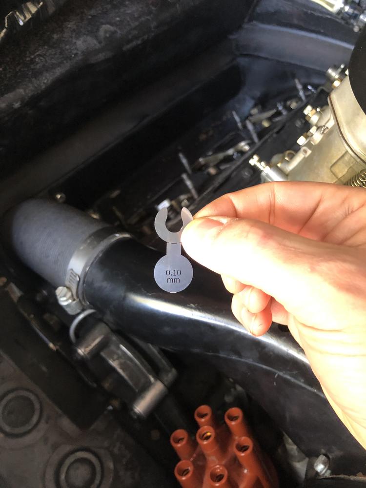
Lock it down:
Snap off (fold back and forth) the tab.
I wiggled and verified the .1mm gap. Very cool and clever solution. No feeler gauges and no mess. Very slick - and I'll add that Brad was incredible to work with and again, highly recommend this system.
THAT BEING SAID - as Perfect as SnapGap is - your adjusters ALSO need to be perfect. If the threads are stretched due to Conan - the locking nut will not lock!
Further, you risk (the pretorque) over snugging the adjuster, forcing you to use a screwdriver to hold it in place (similar to the feeler gauge method).
I had to deal with this on a nearly half of my adjusters. I was pretty upset, but what I did was run an M8x1.0 die over them to clean them up, using a rubber glove around the adjuster (pushed through the glove) to act as a dental dam so-to-speak for any metal shavings.
If it were not for that, I'd have an incredible easy installation - but I ran into problems due to my adjusters being buggered in places.
When going to dig my dies out of the shed - look at what almost got me:
Rusty nail just about went into my foot. My lucky day eh? Phew!!
Near-nail in the foot-experience aside, I wrapped up the snapgap installation:
Then, due to the valve covers being a little grimy, I decided to let them soak up some degreaser in the sun, and then I hit them with my steam cleaner.
After steaming them, it cleaned up them up nice. I then used brake cleaner to remove any residue and then let them dry.
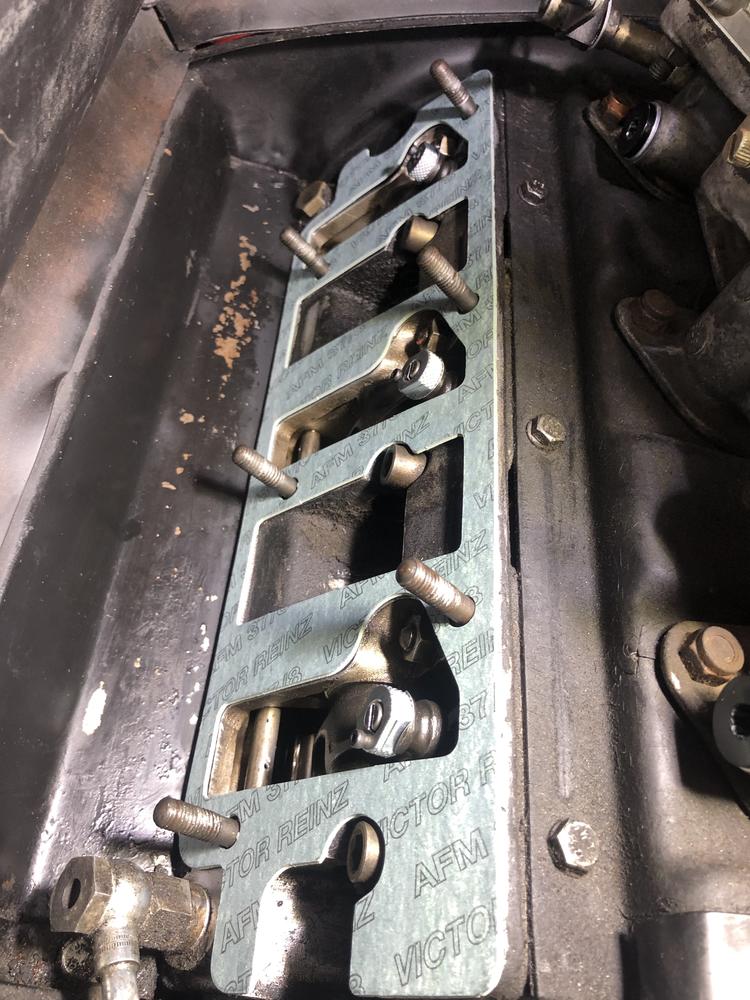
I purchased this set, from Stoddard. I then took a bit of time to clean and prepare the mating surfaces on the engine.
Looks like a great quality set, and I have heard good things about the silicone exhaust manifold gaskets.
Easy installation, star pattern, inside out.
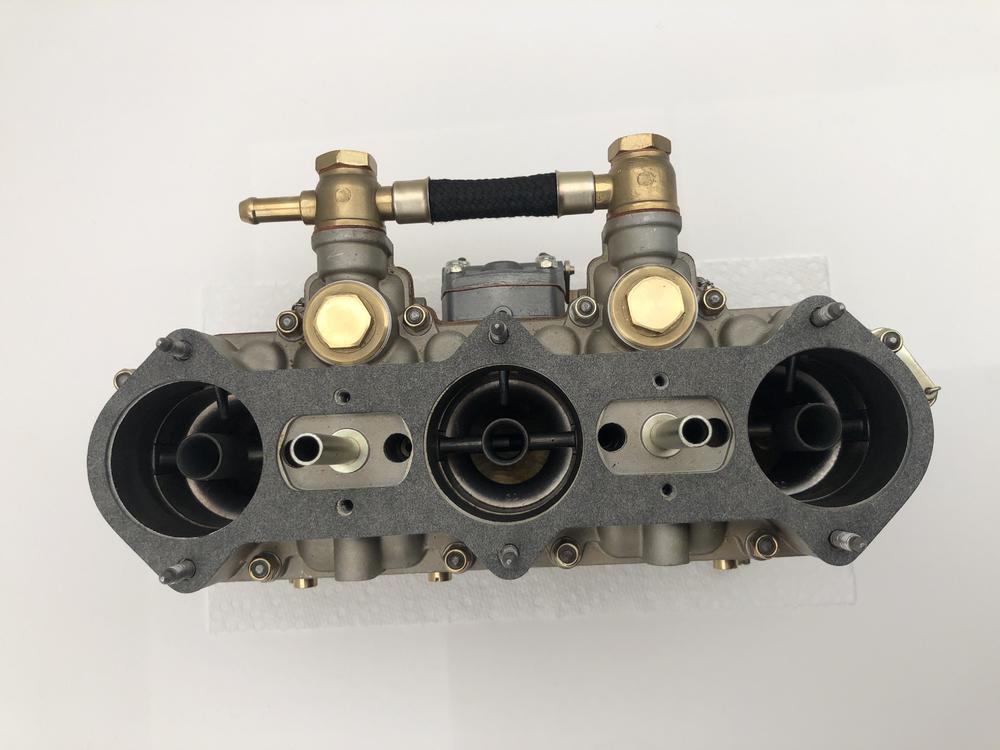
Intake manifolds:
 Posting Permissions

 Reply With Quote